MAX OIL

Loading ...

FLOW CONTROL TOOLS

LANDING NIPPLES AND LOCK MANDRELS

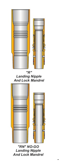
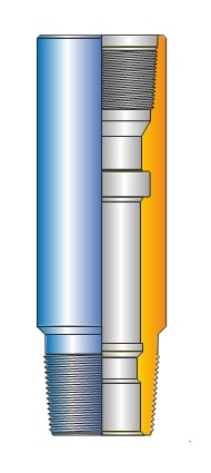
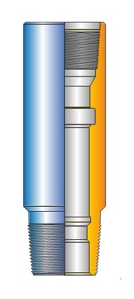
ACT ‘X’ and ‘R’ Landing Nipples and Lock Mandrels ACT ‘X’ and ‘R’ Landing Nipples are run into the well on the completion tubing to provide a specific landing location for subsurface flow control equipment. The common internal profiles of these landing nipples make them universal. ACT ‘X’ Landing Nipple is used in standard weight tubing. ACT ‘R’ Landing Nipple is typically used with heavyweight tubing. The completion can have as many selective nipples with the same ID in and sequence as desired on the tubing string. This versatility results in an unlimited number of positions for setting and locking subsurface flow controls. The flow control, which is attached to the required ACT ‘X’ or ‘R’ Lock Mandrel, is run in the well via the selective running tool on slickline.


ACT ‘XN’ and ‘RN’ No-Go Landing Nipples and Lock Mandrels This equipment is designed for use in single nipple installations or as the bottom nipple in a series of ACT ‘X’ or ‘R’ Landing Nipples. These Landing Nipples have the same packing bore ID for a particular tubing size and weight. ACT ‘X’ and ‘XN’ Landing Nipples are designed for use with standard weight tubing. ACT ‘R’ and ‘RN’ Landing Nipples are designed for use with heavy weight tubing (The ‘N’ designates No-Go Nipples).

Features:

  • Landing Nipples
  • Large bore for minimum restriction
  • Universal nipple with one
  • internal profile
  • Lock Mandrels
  • Retractable locking keys
  • Locks designed to hole pressure from above or below from sudden reversal
  • Optional hold down
  • Interference hold down for smaller locks
  • Shear pin hold down for larger locks
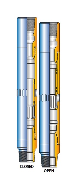
ACT MODEL ‘L’ SLIDING SLEEVE
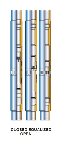
The ACT Model ‘L’ sliding sleeve is a downhole tool used to establish communication, when desired, between the tubing and annulus. Selective and /or top No-Go locking devices are available for use with the sleeve. It has seal bores above and below the ports, and a top No-Go shoulder and locking groove. The ‘L sliding sleeve locates, seals and retains flow control accessories that have either top No-Go or selective locks. ACT Model ‘L’ sliding sleeve is manufactured for standard H2S and H2S –CO services.
Specifications: The ACT Model ‘L’ Bottom Bypass Blanking Plugs are available in the following models:


ACT ‘RPT’ NO-GO LANDING NIPPLE AND LOCK MANDREL
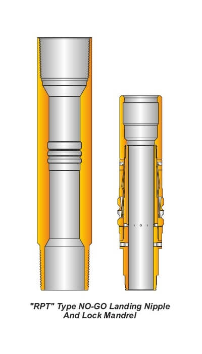
ACT ‘RPT’ No-Go Landing Nipple system provides a mean to run a series of positive location landing nipples in a tubing string with minimum restriction. ACT ‘RPT’ No-Go Landing Nipples are designed to accept ACT ‘RPT’ Lock Mandrels with a rated working pressure of 10,000 psi (690 bar) differential from above and below. ACT ‘RPT’ No-Go Lack Mandrel locates on top of the nipples polished bore, therefore there are no secondary restrictions normally associated with bottom No-Go profiles. This feature makes ACT ‘RPT’ system well suited for high pressure, high volume, large bore completions. ACT ‘RPT’ Lock Mandrels in any given size range are designed to use the same running tool and pulling tool.

Specifications:

NO-GO OD may not be compatible with next larger size nipple.

Features:

  • Large bore
  • Lock Mandrel locates on top of the nipples polished bore
  • Landing nipples can accept PARVEEN’S ‘RPT’ Lock Mandrel with a rated working pressure of 10,000 psi (690 bar) differential from above and below
  • A series of profile ID’s are established for common tubing strings by size and weight
ACT MODEL ‘G’ BOTTOM BYPASS BLANKING PLUGS

The ACT Model ‘G’ Bottom Bypass Blanking Plugs are available in the following models:
‘FSG’-
Run in all model
‘F’ Nipples
‘FWG’-
Run in Top No-Go Model
‘F’ Nipples
‘RZG’-
Run in Bottom No-Go Model
‘R’ Nipples
These type of plugs are run in the by pass position to allow the passage of well fluid through the assembly, while landing the equipment in a Nipple Profile. A ‘C-I’ Running Tool is used to run the plug.
Once sat in the Nipple Profile this group of plugs can hold pressure from above and below. The pressure is equalized prior to retrieval by pulling the Equalizing Mandrel. A standard Pulling Tool and proper Probe for the style of Lock is used to pull the plug assembly. The ACT G’ Bottom Bypass Blanking Plugs are manufactured for Standard, H2S-CO2 service.

Ordering Information:

Please specify nipple model, seal bore size, plug model, working pressure and temperature. Percentage of H2S and Co2.

Applications:

  • Selected zones can be produced or shut in.
  • To pressure test tubing.
  • To isolate tubing for wellhead repair or removal.
  • To set hydraulic actuated packers.
  • To snub tubing in or out of the well.

Specifications:

NO-GO OD may not be compatible with next larger size nipple.

ACT MODEL ‘F’ NIPPLE
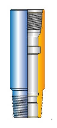
The model ‘F’ nipple provides a tubing lock profile with honed unrestricted seal bore to locate wireline flow control devices such as velocity safety valves, blanking plugs chokes, equalizing check valves and instrument hangers. The number & location of model ‘F’ nipple should be carefully considered in the completion design stage to allow maximum versatility in position of various flow control devices.‘F’ Nipple can accept Selective ‘S’ or Top No-Go ‘W’ locking devices attached to flow control accessories.It is manufactured either from low alloy steel or 9 Cr,1 Mo-steel with controlled hardness for H2S/CO2 service. It is available upto 15,000 psi WP

FOR ORDERING PLEASE SPECIFY:

  • Nipple model
  • Top & bottom thread connections
  • Packing ID
  • Working pressure &
  • temperature
  • Type of service
  • Tubing size, weight & grade
ACT MODEL ‘FB-2’ AND ‘RB-2’ EQUALIZING CHECK VALVES
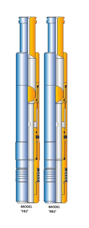
The ACT Model ‘FB-2’ and RB-2’ Equalizing Check Valves are completion equipment, without any Locking Device. These are utilized in the following Tubing Mounted Equipment: ‘FB-2’ run in all Model ‘F’ Nipples and all Model L Sliding Sleeves RB-2’ run in Bottom No-Go ‘R’ Nipples Both models are run into a Nipple Profile and hold pressure from above only. The FB-2’ model lands on the top of an F Nipple Profile seal bore. The RB2 model seats on the Bottom No-Go Shoulder of an ‘R’ Nipple. A ‘C-1’ Running Tool is used to run both valve assemblies. Both models can be equalized prior to retrieval, by shifting open the Equalizing Mandrel Ports. Standard Pulling Tool is utilised for retrieval of these valves. The ACT ‘FB-2’ and ‘RB-2’ Equalizing Check Valves are manufactured for Standard, H2S and H2S-CO2 service.

Applications:

  • Can be used as a plug to pressure test tubing.
  • To set hydraulically actuated packer with the check valve positioned below the packer.
  • For gas lift operations.
  • To be used as a standing valve in wells which have downhole electric pumps.

Ordering information:

  • Please specify nipple model, seal bore size, check valve model, working pressure and temperature, percentage of H2S and Co2.
ACT MODEL ‘R’ NIPPLE

The model ‘R’ nipple is a bottom No-Go style nipple that provides a tubing lock profile with a honed seal bore to locate wireline flow control devices in tubing string. Blanking plugs, chokes, equalizing check valves and instrument hangers which utilize a ‘Z’ lock may be landed in this type of nipple profile. The No-Go shoulder incorporated into the nipple allows positive locating of all flow control equipment used during wireline operations.
ACT nipple is manufactured from low alloy steel/9 CR. 1MO steel with controlled hardness (17-22 HRC) for H2S/CO2 application. It is available up to 15.000 PSI WP.

FOR ORDERING PLEASE SPECIFY:

  • Nipple model
  • Top & bottom thread connections
  • Packing ID
  • Working pressure &
  • temperature
  • Type of service
  • Tubing size, weight & grade
ACT MODEL ‘FGK’ EQUALIZING CHECK VALVE CHOKE WITH CERAMIC BEAN

The model ‘FGK’ equalizing check valve choke is a top No-Go wireline retrievable tool which controls upward flow and prevents downward flow. It is landed and set in the type ‘F’ landing Nipple. An integral, erosion resistant, ceramic orifice is sized to control the upward flow as desired, while downward flow is checked with a ball and seat device. Pressure can be equalized across the valve by breaking the equalizing plug.

SURFACE CONTROLLED SUBSURFACE SAFETY VALVES (SSSV)

ACT model safety valves are installed in the upper wellbore to provide emergency closure of the producing conduits in the event of an emergency. The safety valve system is designed to be fail safe, so that the wellbore is isolated in the event of any system failure or damage to the surface production control facilities. ACT model safety valve is self equalizing, wireline retrievable, surface controlled and flapper type. ACT model Safety Valves are installed in ACT model Landing Nipples.

Features:

  • Self equalizing type
  • Working pressure up to 10,000 psi
  • Sealing and sealing surfaces are out of flow path, when valve is in the open position
  • Solid construction of flapper made from bar stock
ACT MODEL ‘LGK’ EQUALIZING CHECK VALVE CHOKE WITH CERAMIC BEAN

The model ‘LGK’ equalizing check valve choke is a Top No-Go wireline retrievable tool which controls upward flow and prevents downward flow. It is landed and set in the type’L’ sliding sleeve. An integral, erosion resistant, ceramic orifice is sized to control the upward flow as desired, while downward flow is checked with a ball and seat devise. Pressure can be equalized across the value by breaking the equalizing plug.

ACT TUBING RETRIEVABLE SAFETY VALVE

Tubing Retrievable Surface Controlled Sub Surface Safety Valves form part of production string. Hydraulic control line extending from the valve to the Wellhead connects to a part on the outside of the valve. The opposite end of the control line connects to the Wellhead. Hydraulic pressure applied through this control line acts on hydraulic pistons within the valve. The force generated moves the flow tube down against a power spring and tubing pressure, causing the flapper to open. Maintaining this hydraulic pressure allows unrestricted well production through the valve. Releasing the hydraulic pressure causes the flow tube to move up by the action of the power spring, thus allowing the flapper to the closed position.

ACT MODEL ‘LGU’ BYPASS CHOKE

The TYPE ‘LGU BY-PASS CHOKE is a Top No-Go device which is run on wireline and designed to be landed and set in the Type “L” Sliding Sleeve ideally suited for commingled production. The BY-PASS CHOKE is equipped with a ceramic flow choke which controls the flow of the zone being produced through the Sliding Sleeve. Production from the other zone flows through the bypass, but is prevented from back flowing through the choke and the Sliding Sleeve by an API ball and seat back check valve.

SAFETY VALVE LANDING NIPPLE

Safety Valve Landing Nipples are used to accommodate ACT model wireline retrievable sub surface safety valves. These nipples have a locking recess and a hydraulic communication port located between the two polished bores. This nipple features an integral control line connection port which operates Sub Surface Safety Valve.

ACT MODEL ‘B’ DOWNHOLE INSTRUMENT HANGERS

The ACT Model ‘B’ Downhole instrument Hangers are available in the following models:
FSB’
run in all Model
‘F’ Nipples
‘FWB’
run in Top No-Go Model
‘F’ Nipples
RZB’
run in Bottom No-Go
‘R’ Nipples
These type of hangers are used to hang instruments such as Pressure and Temperature Gauges in a Nipple Profile. Recorders are held securely ‘in place when recording data during high production rates. Pressure data is easily correlated between runs, as recorders are always landed at the same depth. The hangers permit simultaneous surveys to be done on several zones at the same time. Standard wireline equipment is used to set and retrieve all three models.
The ACT Model ‘B’ Downhole Instrument Hangers are manufactured for Standard H2S and H2S-CO2 service.

Ordering information:

  • Please specify nipple model, seal bore size, check valve model, working pressure and temperature, percentage of H2S and Co2.
ACT MODEL ‘LGE’ SEPARATION SLEEVE

The model ‘LGE’ Separation Sleeve is a Top No-Go device which is run on wireline and designed to be landed and set in the type ‘L’ sliding sleeve. These are equipped with two packing assemblies, that seal off the upper and lower seal bore of sliding sleeve, Therefore isolating the sleeve ports. Production can be maintained by producing the well through the inside diameter of the tool. The separation Sleeve is also designed with an internal equalizing plug to equalize pressure before retrieving.

SLIP LOCK ASSEMBLY

Application
ACT Slip Lock Assembly is run to lock downhole controls in tubing string run without landing nipple. The Slip Lock can be set at any department in the tubing.

Advantages

  • Run in tubing string without landing nipple
  • Operator can set the lock at any desired depth in the tubing
LOCKOUT TOOL

Lockout Tool is used to shift the Lockout Sleeve of TRSSSV to establish secondary communication in the TRSSSV, thus allowing the WRSSSV to operate within TRSSSV. It is run on Standard Wireline Tool String with the capability of both upward & downward jarring.

SURGE TOOL ASSEMBLY

Application
ACT formation Surge Tool is to be assembled with relevant lock / equalizing assembly. The assembly is to be run in the well bore in a normal manner and device located in relevant nipple. The running tool is to be retrieved prior to utilizing formation surge tool.

Advantages

  • Designed to allow draw-down to be created across the perforations in order to remove debris
  • Can be retrieved by conventional wireline operations, after well pressure is stabilised
DEFORMATION LOCKOUT TOOL

Deformation Lockout Tool is made to permanently lock the TRSSV Wi open position. This tool is a combination mechanical & hydraulic tool. Applied tubing pressure will move the flow tube of TRSSSV downwards keeping the flapper fully open. When tubing pressure is increased further, the deforming dogs will penetrate into the TRSSSV flow tube, making it permanently deformed. This deformation of the flow tube will prevent it fern traveling back into the closed position thus keeping the flapper locked In open postion.

ACT TUBING PACK-OFF ANCHOR ASSEMBLY

These anchors are designed to be set anywhere in the tubing string to straddle and pack-off holes or other communication in the tubing string, so that well production can be continued without pulling tubing. Tubing pack- off anchors are run and set by wireline methods.

ACT MODEL ‘PCMD’ AND ‘PCMU’ SLIDING SLEEVE

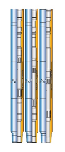
The ACT model PCMD and PCMU sliding sleeve provides a means of communication between the tubing and the annulas. It has internal honed seal bores located at the top and bottom housing for placement of flow control devices. The internal sleeve is shifted open or closed by using a B type wireline shifting tool. For ACT model PCMD. it is down shift to open and for PCMU it is up shift to open sliding sleeve.

CONTROL LINE & ACCESSORIES

Continuous Control Line: A small-diameter hydraulic line used to operate downhole completion equipment such as the Surface Controlled Subsurface Safety Valve (SCSSV). Available in various sizes and materials including Monel for highly corrosive environment. Quick specifications guide is furnished underneath for quick reference. Consult factory for detailed specifications.

ACT MODEL ‘PXD’ AND ‘PXU’ SLIDING SLEEVE

The ACT model PXD and PXU slidwig sleeve provides a means of communication between the tubing and the annulas. It has internal honed seal bores located at the top and bottom housing for placement of flow control devices. The internal sleeve is shifted open or closed by using a B type wireline shifting tool. For ACT model PXD, it is down shift to open and for PXU it is up shift to open sliding sleeve.

STANDING VALVES AND SEATING NIPPLES

ACT Standing valves and companion seating nipples are normally used in intermitting or chamber lift wells at the bottom of the tubing or chamber. The seating nipple is an integral part of the tubing string. The standing valve seats on the No-Go of the seating nipple and seals in the honed bore of the nipple to prevent the fluid from flowing back into well bore when high pressure gas is injected under a slug of fluid. ACT manufactures E-3 type of standing valve, in all popular sizes. A complete line of seating nipples are available to accept the standing valves.

DESCRIPTION & SPECIAL FEATURES OF STANDING VALVE
The E-3 Equalizing Standing Valve has a standard fishing neck and may be equalized and retrieved by wireline. The equalizing feature allows the operator to open ports below the valve and seat without lifting the hydrostatic head. This feature in many cases eliminates the need for an operator to pull a wet string of tubing. This valve may also be used as test plug for testing tubing to check pressure leaks above the valve. Carbide balls are available for severe service in sandy wells.
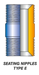
SEATING NIPPLES
The E Seating Nipples are precision nipples that contain a honed bore to accept and seal the standing valve.They are offered in a wide range of sizes compatible with the tubing string and a large selection of bores for different size standing valves.