ACCESSORIES
- MODEL BKR MECHANICAL SETTING TOOL FOR “BKR” SLEEVE VALVE CEMENT RETAINERS AND “B-1” BRIDGE PLUGS
- MODEL FURY 10 HYDRAULIC SETTING TOOL
- MODEL “BP” WIRELINE SETTING TOOLS & COMPACT SINGLE STAGE
- 1.71” OD “SHORTY” SETTING TOOL
- 2-1/8” OD MULTI-STAGE SETTING TOOL
- PRESSURE BLEEDING LOCATIONS1-1/2” 2-1/8” OD SETTING TOOLS
- SIZE 20 WIRELINE PRESSURE SETTING TOOL
- CASING SCRAPER
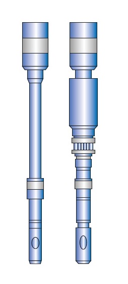
MODEL BKR SEAL NIPPLES – BKR SLEEVE VALVE CEMENT RETAINERS
LOCATOR TYPE:
This unit provides positive control
of the sleeve valve and seals the
tubing to the retainer during
pressuring operations when the need
for anchoring is not warranted. The
tubing can be tested by stinging
into the retainer, then raising the
tubing approximately 4″ at the
retainer, which allows the valve to
be closed and the stinger to remain
sealed off in the retainer bore.
Pressure can then be applied to the
tubing string for testing. To remove
the stinger from the retainer,
simply raise the tubing to free the
stinger from the retainer bore. A
centralizing unit should be run
above to assure the seal nipple
stings in accurately.
FEATURES:
This unit provides positive control
of the sleeve valve and seals the
tubing to the retainer during
pressuring operations while
effectively anchoring the tubing in
the retainer. The tubing can be
tested by stinging into the
retainer, then raising the tubing
approximately 4″ at the retainer,
which allows the valve to be closed
and the stinger to remain sealed off
in the retainer bore. Pressure can
then be applied to the tubing string
for testing.
Release is accomplished by taking an
upward pull of approximately 8,000
lbs. which will collapse the snap
latch and free the seal unit from
the retainer. After repeated usage
the snap-in and snap-out values will
decrease to 2,500 lbs. snap-in and
5,000 lbs. snap-out force. A
centralizing unit should be run
above to assure the seal nipple
stings in accurately.
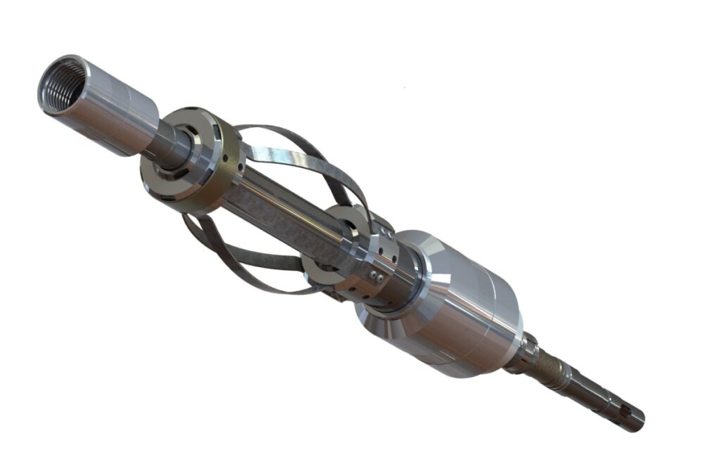
MODEL BKR MECHANICAL SETTING TOOL FOR “BKR” SLEEVE VALVE CEMENT RETAINERS AND “B-1” BRIDGE PLUGS
The Model BKR Mechanical Setting Tool is designed to run and set a Model BKR Sleeve Valve Cement Retainer and Model BKR-1 Bridge Plug. It is easy to operate and has low maintenance. The setting tool can be converted for 4 1/2 through 13 3/8” casing sizes. This tool incorporates both a stinger seal and built-in snap latch allowing the tool to be latched into the retainer with set-down weight and released with up-strain and/or right hand rotation. This tool can be run time after time by simply moving the drive housing into the running position. Disassembly is not required every time.
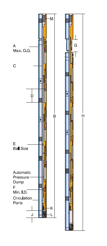
MODEL FURY 05 HYDRAULIC SETTING TOOL
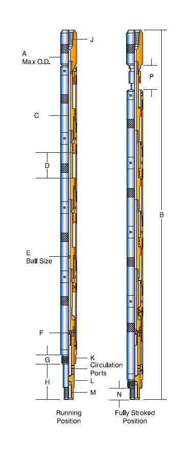
MODEL FURY 10 HYDRAULIC SETTING TOOL
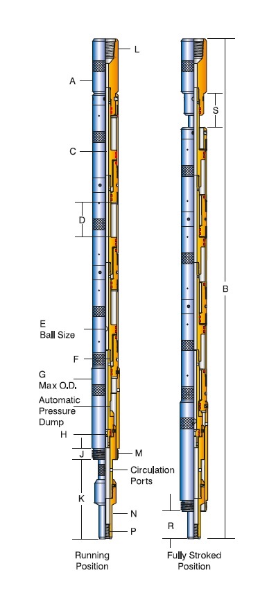
MODEL FURY 20 HYDRAULIC SETTING TOOL
MODEL “BP” WIRELINE SETTING TOOLS & COMPACT SINGLE STAGE
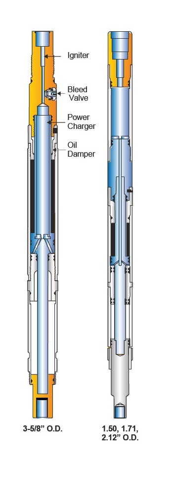
Model “BP” wire line pressure setting tools are compact tools inside which the ignition and burning of a pyrotechnic power charge (manufactured by TITAN SPECIALTIES, Pampa, Texas) produces gas pressure that elongates the tool. This provides the stroke and force necessary to set and anchor conventional bridge plugs, packers, and cement retainers provided by various manufacturers. The tools feature pressure balanced top and bottom pistons to eliminate presetting of the mentioned products caused by high hydrostatic well pressure.
OPERATION:
An electrically actuated high
temperature rated igniter (also
manufactured by TITAN SPECIALTIES)
located at the upper end of the tool
is ignited and produces a flash
flame which, in turn, ignites the
power charge that is located
directly below the igniter. The
power charge, which is constructed
of carefully controlled combustible
elements, begins a slow burn lasting
approximately 30 seconds. The
resultant gas derived from the
burning charge gradually builds to
high pressure and causes the tool to
elongate. The pressurized gas
migrates down the center of the top
piston and out into an annular
cavity formed between the top piston
and connector sub.
The pressure acting on this area
drives the outside of the tool
(consisting of top and bottom
cylinders) downward while the top
and bottom pistons remain
stationary. This motion anchors the
bridge plug to the casing i.d. then
pulls the shear stud of the bridge
plug apart, freeing the setting tool
for removal from the well. An oil
damper system is built into the tool
to control the speed at which the
tool strokes. As the tool elongates,
this oil is forced through an
annular orifice and out of the tool
at a controlled rate and prevents
the tool from stroking too fast,
causing damage to the tool once the
shear stud has parted.
NOTE:
It is mandatory that the tool be
filled to capacity With oil each use
or damage to the tool will result.
Excess oil will be purged out
automatically during assembly.
Likewise, oil expansion caused by
high well temperature during running
will be purged in the same manner.
In wells where hydrostatic pressure
is less than 10,000 psi, all tool
sizes are available with manual
bleeder valve assemblies. This valve
provides a safe, easy method of
bleeding trapped gas pressure from
the tool before disassembly is
begun. When bottom hole pressures
exceeding 10,000 psi are to be
encountered, the manual bleeder
valve and its corres ponding sub are
replaced by a portless sub. Bleeding
is then accomplished by backing the
firing head out of the setting tool.
Both methods of bleeding pressure
are illustrated in the disassembly
steps found later in this manual.
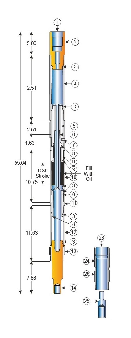
1.50” OD “SHORTY” SETTING TOOL
Vendor Power Charges and Igniters
for use with this tool:
Power Charges: Titan Specialties,
Pt. No. 6000-000-171-1S Owen Oil
Tools, Inc. Pt. No. JEC-5302-041
Igniters: Titan Specialties, Pt. No.
6035-000-050 Owen Oil Tools, Inc.
Pt. No. DET-5306-074
Tool total stroke: 6.36 in.
Tool piston area: 1.11 in.²
Tool max. Pull: 13,000 lbs. At 4.25
inch stroke Unported tool max.
Hydrostatic pressure: 15,000 P.S.I.
Ported tool max. Hydrostatic
pressure: 10,000 P.S.I.
ACT, Inc. Wireline pressure setting
tools are constructed from high
quality alloy steel with traceable
heat numbers. Material hardness is
also controlled. The illustrations
shown above list suggested critical
minimum and maximum wear diameters.

1.71” OD “SHORTY” SETTING TOOL
Vendor Power Charges and Igniters for use with this tool:
Power Charges: Titan Specialties, Pt. No. 6000-000-171-1S Owen Oil Tools, Inc. Pt. No. JEC-5302-041
Igniters: Titan Specialties, Pt. No. 6035-000-050 Owen Oil Tools, Inc. Pt. No. DET-5306-074
Tool total stroke: 6.36 in.
Tool piston area: 1.11 in.²
Tool max. Pull: 13,000 lbs. At 4.25 inch stroke Unported tool max. Hydrostatic pressure: 15,000 P.S.I. Ported tool max. Hydrostatic pressure: 10,000 P.S.I.
ACT, inc. Wireline pressure setting tools are constructed from high quality alloy steel with traceable heat numbers. Material hardness is also controlled. The illustrations shown above list suggested critical minimum and maximum wear diameters
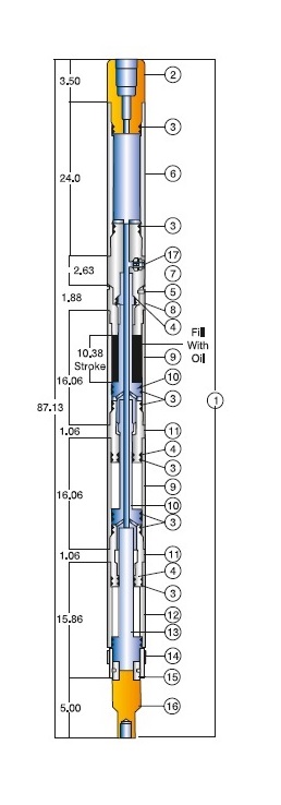
1.718” OD MULTI-STAGE SETTING TOOL
ACT, Inc. Wireline pressure setting tools are constructed from high quality alloy steel with traceable heat numbers. Material hardness is also controlled. The illustrations shown above list suggested critical minimum and maximum wear diameters.
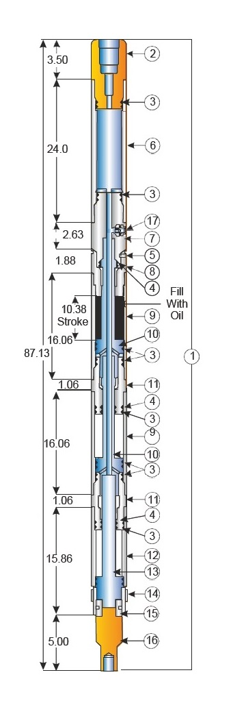
2-1/8” OD MULTI-STAGE SETTING TOOL
ACT, Inc. Wireline pressure setting tools are constructed from high quality alloy steel with traceable heat numbers. Material hardness is also controlled. The illustrations shown above list suggested critical minimum and maximum wear diameters.
Tool total stroke: 10.36 in.
Tool piston area: 3.6 in.²
Tool max. Pull: 30,000 lbs. At 6.91 inch stroke Unported tool max. Hydrostatic pressure: 15,000 P.S.I. Ported tool max. Hydrostatic pressure: 10,000 P.S.I.
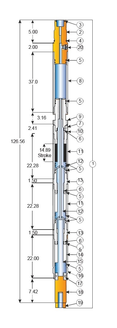
3-1/4” OD MULTI-STAGE SETTING TOOL
Tool total stroke: 14.8 in.
Tool piston area: 7.66 in.²
Tool max. Pull: 72,000 lbs. At 9.0 inch stroke
Ported tool max. Hydrostatic pressure: 10,000 P.S.I.
PRESSURE BLEEDING LOCATIONS1-1/2” 2-1/8” OD SETTING TOOLS
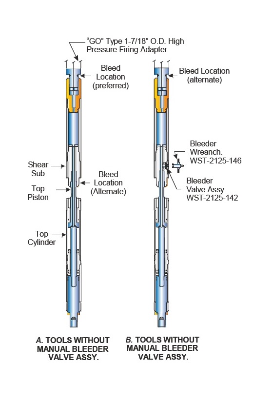
ACT, Inc. wireline pressure setting tools in O.D. sizes 1-1/2” through 2-1/8” do not contain a Baker style manual bleeder valve assembly (ACT pt. no. WST-2125-142) except when specifically ordered. Two locations for bleeding pressure from tools less manual bleed valves are illustrated in drawing “A”. The preferred method of bleeding pressure is to hold wrench on “GO” 1-1/2” O.D. high pressure firing adapter while turning the setting tool counter clockwise. Pressure will begin to bleed as soon as the lower o-ring on the firing adapter is uncovered. Ample threads are provided on the firing adapter. Should a bridge occur and pressure stops bleeding, screw the tool clockwise then begin the procedure again.
The alternate method shown in drawing “A” is accomplished by holding wrench on shear sub (see parts list) while turning the top cylinder counter clockwise. The top piston will back out of shear sub and pressure will begin to bleed. Again, if a bridge occurs screw the tool clockwise then begin the procedure again. An indication that most of pressure has safely bled off is when the tool partially closes. This indicates that the trapped compressed atmosphere in bottom cylinder is overcoming what little gas pressure remains of the power charge.

SIZE 10 WIRELINE PRESSURE SETTING TOOL

SIZE 20 WIRELINE PRESSURE SETTING TOOL
SHEAR-OUT SAFETY JOINT
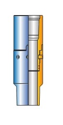
ACT shear-out safety joint enables the positive release of the tubing string in completions with expected retrieval challenges. The joint is used between packers in single, dual, and triple completions. It is also used when rotational release is not wanted. The safety joint is easily adjusted in the field for various straight-pull release shear values. It can also be adjusted to compensate for hydraulic conditions that exist when the string is landed or conditions that are created by well treatment. These safety shear joints are keyed so torque through the tool does not load the shear screws. (Non-keyed versions are also available).

CASING SCRAPER
FEATURES:
- Made from high quality low alloy steel.
- Fully heat treated to give max. strength and hardness.
- Can withstand rough use and is rugged to give long life. Scraping edge is designed to be effective in full circumference clean out.
- Precision machined blades to fit casing profile.
- Available with API Monogram.Available with API Monogram.
- Available with API Monogram.
- Blades are properly tapered to the tool body to minimize the possibility of the scraper hanging up inside the casing.
- Blades are properly tapered to the tool body to minimize the possibility of the scraper hanging up inside the casing.
FUNCTIONAL PURPOSE The Casing Scraper is used for removing the stuck mud cement embedded bullets, perforation burrs, rust, mill scale, paraffin and similar unwanted material from the inside wall of the Casing.
OPERATIONAL HIGHLIGHTS For removal of the Cement Sheath the Scraper should be installed between the Drill Bit and the Drill Collar so that both the drilling out and the sheath removal can be accomplished at the same time. It is a good practice to maintain circulation while these operations are being conducted. For removal of perforation burrs and bullets, the scraper is installed pin up on the first joint of the drill pipe with an old three cone rock bit installed in the box end of the scraper.
